
Arduino: build alarm clock - how it works
In this practical tip, you will learn how to build an alarm clock with the Arduino. It's easy with the right code.
Arduino: build alarm clock - how it works
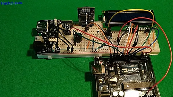
For an Arduino alarm clock you need a power supply, an IR receiver with remote control, a buzzer, a DS3231 real-time module, a thermistor, an LCD and of course a breadboard and an Arduino with matching jumper cables.
- First plug the power supply the right way around on the breadboard and make sure that it is set to 5 volts on both sides.
- Connect the infrared receiver to the plus and minus bars and to pin 3.
- Connect the active buzzer to pin 13 and to the ground (minus bar).
- The DS3231 module is also connected to the plus and minus bars. Also connect SDA to SDA and SCL to SCL on the Arduino.
- Now you need the thermistor, which is also connected to 5 volts and to analog 0 via a 10 kOhm resistor.
- Finally, you have to connect the LCD. K is connected to - and A to +. Pins D4 through D7 connect to pins 9 through 12 on the Arduino. Now you have to connect E to pin 8, RW to the minus bar and RS to pin 7. Connect pin V0 to a 10k potentiometer, which is connected to 5V and ground. Finally, connect VDD to 5V and VSS to the ground.
Program the Arduino alarm clock
If you've set everything up properly, you can program the Arduino alarm clock. We have written a small sample code for this:
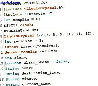
- #include #include #include #include "IRremote.h" int tempPin = 0; DS3231 clock; RTCDateTime dt; LiquidCrystal lcd (7, 8, 9, 10, 11, 12); int receiver = 3; IRrecv irrecv (receiver); decode_results results; int alarm; boolean alarm_state = false; String hour; String destination_time; String minute; String current_time; int buzzer = 13; void translateIR () {switch (results.value) {case 0xFFA25D: alarm_state =! alarm_state; break; // POWER case 0xFFE21D: break; // FUNC / STOP case 0xFF629D: break; // VOL + case 0xFF22DD: break; // FAST BACK case 0xFF02FD: break; // PAUSE case 0xFFC23D: break; // FAST FORWARD case 0xFFE01F: break; // DOWN case 0xFFA857: break; // VOL- case 0xFF906F: break; // UP case 0xFF9867: break; // EQ case 0xFFB04F: break; // ST / REPT case 0xFF6897: alarm = 0; add (); break; // 0 case 0xFF30CF: alarm = 1; add (); break; // 1 case 0xFF18E7: alarm = 2; add (); break; // 2 case 0xFF7A85: alarm = 3; add (); break; // 3 case 0xFF10EF: alarm = 4; add (); break; // 4 case 0xFF38C7: alarm = 5; add (); break; // 5 case 0xFF5AA5: alarm = 6; add (); break; // 6 case 0xFF42BD: alarm = 7; add (); break; // 7 case 0xFF4AB5: alarm = 8; add (); break; // 8 case 0xFF52AD: alarm = 9; add (); break; // 9 case 0xFFFFFFFF: break; default: break; } delay (500); } void add () {destination_time + = String (alarm); } void setup () {pinMode (buzzer, OUTPUT); lcd.begin (16, 2); clock.begin (); clock.setDateTime (__ DATE__, __TIME__); irrecv.enableIRIn (); } void loop () {int tempReading = analogRead (tempPin); double tempK = log (10000.0 * ((1024.0 / tempReading - 1))); tempK = 1 / (0.001129148 + (0.000234125 + (0.0000000876741 * tempK * tempK)) * tempK); float tempC = tempK - 273.15; float tempF = (tempC * 9.0) / 5.0 + 32.0; dt = clock.getDateTime (); lcd.setCursor (0, 0); lcd.print (clock.date format ("dmY H: i: s", dt)); lcd.setCursor (0, 1); lcd.print (String (tempC) + "" + String ((char) 223) + "C"); if (irrecv.decode (& results)) {translateIR (); irrecv.resume (); } hour = clock.dateFormat ("H", dt); minute = clock.dateFormat ("i", dt); current_time = hour + minute; if (current_time == destination_time && alarm_state == true) {pinMode (buzzer, HIGH); } else {pinMode (buzzer, LOW); } if (alarm_state == true) {lcd.setCursor (10, 1); lcd.print ( "!"); } else {lcd.setCursor (10, 1); lcd.print (""); } if (destination_time.length () == 4) {lcd.setCursor (11, 1); lcd.print (destination_time); } else if (destination_time.length () <4) {lcd.setCursor (11, 1); lcd.print ( "TYPE"); } else {lcd.setCursor (11, 1); lcd.print ( "TYPE"); destination_time = ""; } delay (1000); }
- Tip: Copy this code into your IDE and adapt it as required. You can find a detailed explanation of the code lines in our picture gallery.
In the next article, we will explain how you can control a GSM module with the Arduino.
Latest videos
First, all important libraries are imported. A variable is also defined for the pin to which a thermistor is connected. Then objects are defined for the RTC module and LCD, and instances and variables are created that will become important afterwards.
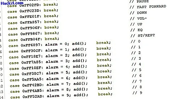
Furthermore, define a new void method that executes certain commands depending on the signal received. If you press the power button on the remote control, the value of the boolean variable "alarm_state" is reversed. However, if you press one of the numbers, this number is saved under the "alarm" variable and the add method is executed.
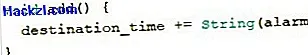
The add method adds the string of this number to the initially empty string "destination_time".
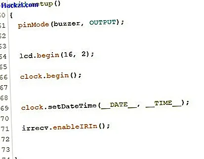
In the setup method you define the buzzer as an output. The LCD and the clock are also started. Finally, the sketch compiling time is set and the IR receiver is started.
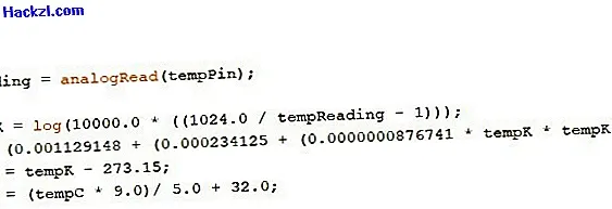
In the loop method, the value of the thermistor is read out and converted into degrees Celsius.
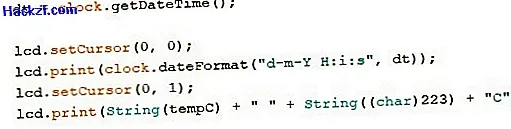
The current time is also obtained from the RTC module and displayed on the LCD together with the room temperature.
Now it is checked whether an IR signal has been received. If this is the case, the previously defined method is carried out. The hours and minutes are again obtained from the RTC module and put together to form a string.

If the current time corresponds to the wake-up time and if the wake-up was previously activated, the buzzer beeps for one minute.

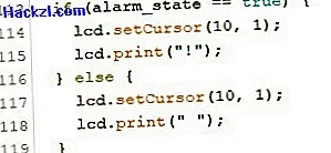
When the alarm clock has been activated, an exclamation mark also appears on the display.
The wake-up time is also shown on the LCD if it has four digits.