
WLAN on the Arduino - connect the ESP8266-01 to the Arduino and control NodeMCU Amica remotely with your smartphone
The Arduino is one of the best known developer boards. Unfortunately, the standard models do not have a Wi-Fi chip installed. This practical tip shows you how to connect an ESP8266-01 WLAN module to the Arduino and how you can remotely control the NodeMCU Amica with your smartphone.
Control NodeMCU Amica with your smartphone
The NodeMCU Amica has a variety of pins, as well as a built-in ESP8266 Wi-Fi chip and a microUSB socket. Therefore, it makes sense to use the device more as a standalone device. How to connect a "classic" ESP8266 board to the Arduino is described later in the article.
- To be able to program ESP chips, you must first download and install the drivers for all CP210er chips from Silicon Labs. Fortunately, this happens relatively quickly.
- Then open the Arduino IDE and go to Settings. Add the URL "//arduino.esp8266.com/stable/package_esp8266com_index.json" (without quotation marks) to the additional board administrator URLs. Then start the board administrator, enter "ESP8266" and install the package.
- Also go to the library manager, enter "Blynk" and install the latest version. All the necessary components are now installed.
- You need the Blynk app to control the NodeMCU with your smartphone. If not already done, create a new account here or log in with an existing one. Then create a new project and select the NodeMCU as the board.
- With the sample codes in the Arduino IDE you should also find a code for Blynk (→ "Boards_WiFi") on the NodeMCU. Simply enter the Blynk token of your project here, which you have been automatically sent by email. Also enter your SSID and password.
- In order to load the code onto the board, you must of course select it from the "Tools" tab. In our case "NodeMCU 1.0 (ESP12E Module)" had to be selected, the frequency 80 MHz, the memory size "4M (3M SPIFFS)" and the baud rate 115200. However, please note that the information may differ depending on the model.
- You can then simply load the code onto the board and control it with the Blynk app. Here you can easily create different widgets and, for example, control an LED with a button.
Connect WiFi on the Arduino - ESP8266-01 to the Arduino
Next we want to connect and use the ESP8266-01 module with the Arduino.
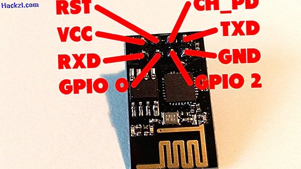
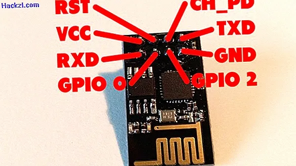
- If you turn the board so that it points down with the golden antenna, you can find the VCC pin in the top left, which of course has to be set to HIGH. To the right is the RST pin, which you usually do not need to use. The CH_PD pin next to it must also be set to HIGH again. At the top right we have the TXD pin that outputs signals and at the bottom left we have an RXD pin that receives the signals, of course. We also have GPIO0 and GPIO2, as well as the classic ground pin, which is located at the bottom right.
- In order to be able to use the module on the Arduino, it makes sense to use SoftwareSerial, since HardwareSerial is mostly used for communication between the Arduino and PC. In our case, however, the module uses 115200 as the baud rate, which means that communication between the ESP and the Arduino via SoftwareSerial is not possible.
- To change the baud rate, many users simply flash new firmware that provides a different baud rate. However, this is not absolutely necessary since the baud rate can also be changed using a command. This command is "AT + UART_DEF". Other commands such as "AT + IPR" or "AT + CIOBAUD" can also be found on the Internet, but this is not advisable, since "AT + IPR" in particular can also crash the module.
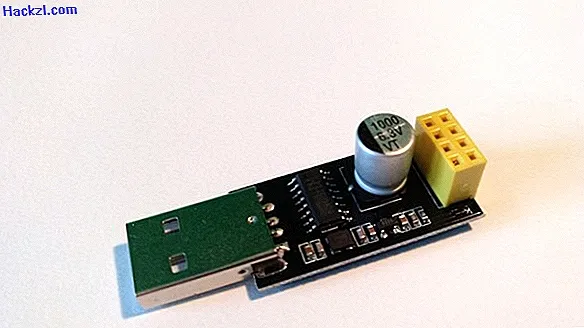
- To send the command to the module, it is recommended to connect it to the PC with a USB adapter, which is usually supplied free of charge or can be found on the Internet for around one euro. If you don't have a USB adapter, you can either order one online, which is highly recommended, or use a universal FTDI adapter, which is quite complex and often doesn't work properly. Alternatively, there is another variant that will be explained later.
- If you have connected the module with the adapter to the PC, you can send the command "AT + UART_DEF = 9600, 8, 1, 0, 0" with the baud rate 115200 and CR + LF. You can then reconnect the module and send commands at the baud rate 9600.
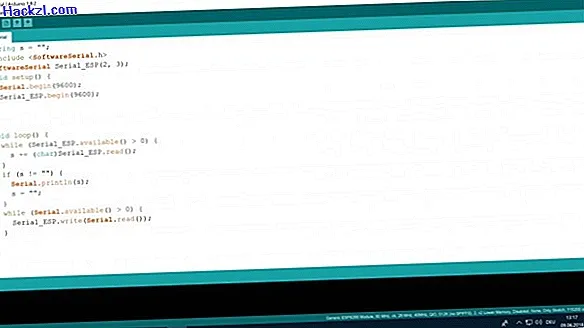
- Next you have to program the Arduino. The code is relatively simple. We first define an empty string with the command »String s =" ";«, import SoftwareSerial (»#include«) and create a new SoftwareSerial object (»SoftwareSerial Serial_ESP (2, 3);«). In the setup method, the connection to the ESP (»Serial_ESP.begin (9600);«) and the connection to the PC (»Serial.begin (9600);«) is started. If the ESP sends a signal, this is added to the string and the string is then output in the serial monitor (»while (Serial_ESP.available ()> 0) {s + = (char) Serial_ESP.read ();} if (s ! = "") {Serial.println (s); s = "";} «). Conversely, signals sent by the serial monitor, i.e. the PC, are also passed on to the ESP ("while (Serial.available ()> 0) {Serial_ESP.write (Serial.read ());}"). However, it is very important that the whole thing is converted into a char, since the ESP sends numbers back. You can also find the code again in the picture gallery at the end of the article.
- Once you've loaded the code onto the Arduino, you need to connect the ESP. Caution! The ESP uses 3.3 volts instead of 5V. 5V break this completely. However, since the Arduino works with 5V logic, the voltage has to be adjusted accordingly.
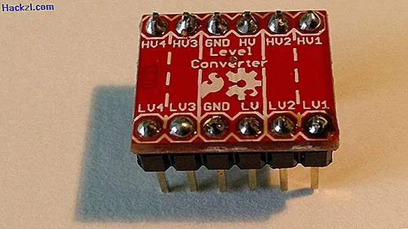
- In theory, you can use a voltage divider with resistors, but in practice the whole thing is quite imprecise and can easily be disturbed. Therefore, you need to switch a logic level converter between the Arduino and the ESP.
- Connect the 5V pin of the Arduino to the HV, i.e. high-voltage pin on the converter, and the LV pin of the converter to the VCC pin of the ESP. Also connect the LV pin in parallel to the CH_PD pin of the ESP so that the chip is also switched on. Also, in order to get enough current, you should connect the 3.3V pin of the Arduino to the LV pin of the converter, thus consequently to the VCC and CH_PD of the ESP. Now connect the TX pin from SoftwareSerial - in our case pin 3 on the Arduino - with HV 1, 2, 3 or 4 and the opposite LV pin with the RXD pin on the ESP. Repeat this step for the RX pin of the Arduino as well.
- Finally, you have to connect the ground. To do this, connect the ground of the Arduino to the ground on the HV side of the converter. Then connect the ground on the LV side to the ground of the ESP. Finally you have to connect the HV ground and the LV ground.
- Now you can easily send AT commands with your PC to the ESP via the Arduino. You can easily connect the Arduino to your WiFi, create a web server and much more. Simply add the respective AT commands to the Arduino code (in the setup method) that are to be sent to the ESP, which you can also find in the "AT Instruction Set".
- If you do not have a USB adapter ready, you can also send the command to change the baud rate via HardwareSerial using the same circuit, using the Arduino's TX and RX pins, i.e. 0 and 1. However, do not forget to adjust the baud rate in the code accordingly.
In the next practical tip, we will give you an introduction to the Java programming language.
Latest videos
With the NodeMCU Amica you can easily control electronic components with your smartphone.

Connect the WiFi on the arduino esp8266 01 to the arduino and control nodemcu amica remotely with your smartphone

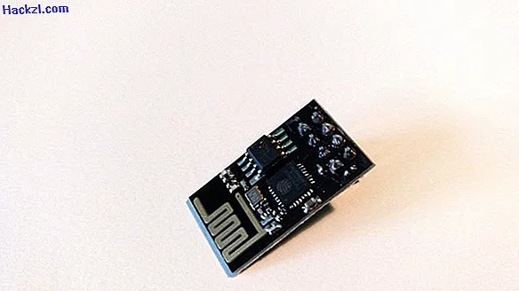
With the ESP8266-01 board, you can also use WLAN on classic Arduinos.
You need a USB adapter to change the baud rate.
Connect the WiFi on the arduino esp8266 01 to the arduino and control nodemcu amica remotely with your smartphone

Alternatively, you can also use a universal FTDI adapter, which can be more complicated.

Since the Arduino works with 5V logic, you need to level the voltage down.
Connect the WiFi on the arduino esp8266 01 to the arduino and control nodemcu amica remotely with your smartphone
Connect the module to your Arduino.

Use the following code to communicate.